Troubleshooting Small Engines
Introduction
There are five systems at work in every small engine: - Fuel supply,
- Compression,
- Ignition,
- Lubrication and cooling,
- Governor (speed control).
Each of these systems is explained in depth in the following pages. Two other common systems—- Starter systems, which require a battery, starter motor, and electrical recharging system, and
- Brake systems, which stop the engine if you let go of the controls—are also discussed in detail.
In short, these five systems generate the power to spin a blade, turn a wheel, or perform other work, while the two others—starters and braking systems—increase safety and convenience. The following pages will familiarize you with the major parts in these systems and the essentials of how they work.
The building block of a small engine consists of the following: Cylinder Head, Cylinder Block, Sump (horizontal shaft, vertical shaft)
- Fuel supply,
- Compression,
- Ignition,
- Lubrication and cooling,
- Governor (speed control).
- Starter systems, which require a battery, starter motor, and electrical recharging system, and
- Brake systems, which stop the engine if you let go of the controls—are also discussed in detail.
Module 1 - Engine Operation and Theory
4 Cycle Theory Certification
Brigs and Stratton ID System
Module 2 - Engine Compression Diagnosis & Repair
Engine details
Module 3 - Fuel Systems and Carburetors
Fuel Systems and Carburetors
Reading Adjustments
Module 4 - Governor System
Module 5 - Ignition System and Electric
Lab – Safety Glass, Gloves, Electrical Tester/Multi Meter, Cylinder leak tester, flywheel puller
Module 1 - Engine Operation and Theory
Blower Housing
In front of Blower housing is – Model Type and Code (for parts replacement)
9L502 = 9 Cubic Inch, L series, 5=Crankshaft (vertical/Horizontal), Carburetor, vacuum governor bearing, 2= type of starter (rewind string)
DOM = Date of Manufacture
Where in manual to find torque spec (Foot/Pound)
Starter Motor/Rewind
Unique shape with flywheel and fins – blow air on cylinder and head fins dissipating heat, prevents overheating
Internal Combustion Engines
They are 2 types:
- 4 Stroke Engine - Intake, Compression, Power, Exhaust (2 crankshaft revolution) Uses Valves
- 2 Stroke Engine - Power Stroke one revolution of Crankshaft - Uses Ports
- The end of the combustion stroke and the beginning of the compression stroke happen simultaneously, with the intake and exhaust (scavenging) functions occurring at the same time.

Cylinder Head
OVA Overhead Valve
Rocker arm, push rods, tappets, exhaust valve, intake valve, springs
There are 2 types of Valves - Flat Head and Over Head

Some of the vital causes for a lawn mower engine to surge
Bad gas
Bad spark plug
Dirty / faulty carburetor
Dirty Air Filter
Gasket vacuum leak
Governor control fault
Cylinder Block
Cylinder, Piston, Rings( oil rings, compression rings, scraper ring, Goguen pin, connecting rod
Crankshaft, bearing (main, journal)
Camshaft
Timing Gears
Carburetor - Venturi, Choke, Throttle
Airbox, Air filter
Governor
Flywheel,
Fuel Tank
Ignition System
Sparkplug
Spark plug, Ignition coil, flywheel permanent magnet
Recoil, Starter, Battery
Sump - Drain plug
Cup/Flywheel
Flywheel operates weathervane (springs brings it back when it slows down) it controls the governor/carburetor throttle
It controls constant speed of the engine
Works in conjunction with governor spring and idle spring
Flywheel made of aluminum on lawn mower made of cast iron
Aluminum flywheel isn’t heavy enough to maintain momentum of piston going up and down in cylinder, so the flywheel and lawnmower blade is part of flywheel to maintain momentum.
Flywheel fins are not the same in height – it change the harmonics.
Inside flywheel are magnets and as the flywheel spins, it passes in front of a stationary coil, builds up a magnetic field and as it passes the coil it collapse the field and induce a charge to the spark plug where we get our ignition.
2 types of timing
Electrical - Ignition
Mechanical – Flywheel Key - Fuel at the right time, Valves at the right time, spark at the right time, piston at the right time – all maintain with the Flywheel key.
Crankcase Breeder Cover
It release the pressure in the bottom of the crank case, unburn fuel coming from the valve guides
It has the valve and a port to the carburate to reburn those unburn gases.
Air fuel tube to carburetor
Essential for combustion are:
Compression
Engine Oil/Pistons/Rings/Connecting Rods/Crankshaft/Camshaft/Timing/Rocker Arm
Sparks -Spark Plug/Ignition Coil
Fuel - Gasoline/Carburetor(Choke/Run)/Air Filter
Module 2 - Engine Compression Diagnosis & Repair
Lawn mower, pressure washer, chain saws, generator motors
Issue- fuel starvation or too lean
Engine surging, hunting, waffling, RPM going up and down
Carburetor - Idle screw, pilot jet with 13 thou drill bit thru hole
Fuel to Rich
Stuck Valve
Some of the vital causes for a lawn mower engine to surge
Bad gas
Bad spark plug
Dirty / faulty carburetor
Dirty Air Filter
Gasket vacuum leak
Governor control fault
The Compression System
The inventors of the first internal combustion engines discovered that fuel burns more efficiently if compressed in a sealed chamber before burning it. Compression of the air-fuel mixture in the small 4-stroke engine begins as the intake valve closes (or as the piston covers the cylinder ports on a 2-stroke mill). The trapped vapors are pushed toward the cylinder head by the piston and compressed into a space about one-sixth their original volume. The exact amount of compression is an indicator of an engine’s efficiency. That’s why a tightly sealed combustion chamber is so important for good engine performance.
VALVES ON A 4-STROKE ENGINE
Valves located in the combustion chamber let fuel vapors and air enter the cylinder and let exhaust gases exit at precisely timed intervals. A typical 4-stroke small engine contains one intake valve and one exhaust valve per cylinder, and most small 4-stroke engines have one cylinder and use an L-head (or flathead) design, where the valves are installed in a valve chamber next to the piston. Overhead valve (OHV) designs offer greater efficiency, however, and are increasingly popular with consumers. In this design, the valves are located in the cylinder head directly in line with the piston and are moved by pivoting rocker arms.
PISTON
The piston rides through the cylinder, much as a plunger rides through the chamber in a hand-operated air pump. At the appropriate moment, the cylinder is sealed so that the air-fuel mixture is compressed as the piston moves toward the cylinder head. When the mixture is ignited, rapidly expanding gases force the piston back down through the cylinder. While 4-stroke engines typically have flat-topped pistons, 2-stroke owners getting into their engines will discover pistons with an exhaust deflector cast into the piston crown.
RINGS
The piston diameter is narrow enough to permit a thin space around it for a coating of oil. Flexible piston rings, installed in grooves in the piston, work in concert with the oil to create a seal between the piston and the cylinder wall, thus ensuring good compression. As the piston is pushed down through the cylinder by expanding gases, a connecting rod transfers the force of those gases to the flywheel. It’s the flywheel’s momentum that perpetuates the engine’s 4-stroke cycle.
COMPRESSION PROBLEMS
Too little or too much compression can damage pistons, rings, valves, valve guides, valve seats, and the cylinder wall. Loss of recommended compression (measured in pounds per square inch) can prevent an engine from starting at all. On a 4-stroke, if an exhaust valve leaks, exhaust can back up into the cylinder, causing premature wear. Too much compression can cause the air-fuel mixture to burn too fast, causing knocking or pinging. Excess compression can also leave carbon deposits that further aggravate problems.
Module 3 - Fuel Systems and Carburetors
There are 3 components in the carburetor. Namely;
Venturi
Fuel jet
Gasoline storage room
AFM (Air Fuel Mixture), AFM has ratio about 14 : 1. It mean, 14 air molecules and 1 fuel molecule.

Carburetor
- Fuel from the external fuel tank is supplied to the float chamber.
- Fuel from the float chamber is supplied to the main nozzle which is a part of the jet tube.
- The engine sucks air from the atmosphere through the choke valve. This air passes through the venture, it causes a reduction of the area of a cross-section at the throat of venture.
- Venture action - pressure at the main nozzle decreases; velocity of air increases.
- Differential pressure -induced at the float chamber and the main nozzle causes the mixture of fuel and incoming atmospheric air.
- Increased velocity of air after the venture partially vaporize the engine fuel which is then totally evaporated by the heat in the intake manifolds of the combustion chamber and cylinder walls.
- Open the throttle valve present at the bottom of the jet tube, it allows more air flows through the venture tube and a more quantity of the air-fuel mixture is supplied to the engine, causes, the engine develops more power.
- Close the throttle valve, reverse action takes place and the power of the engine reduces.

Engine RPM's Surge Up And Down- "If your lawnmower’s engine is surging it could be a problem with the carburetor.
The carburetor mixes air and fuel to the perfect ratio for combustion. There are passages and nozzles (called jets) that route the fuel through the carburetor.
The jets meter the precise amount of fuel that is needed for combustion.
The jets have tiny openings that can easily be clogged by dirt or from corrosion caused by old fuel sitting in the carburetor.
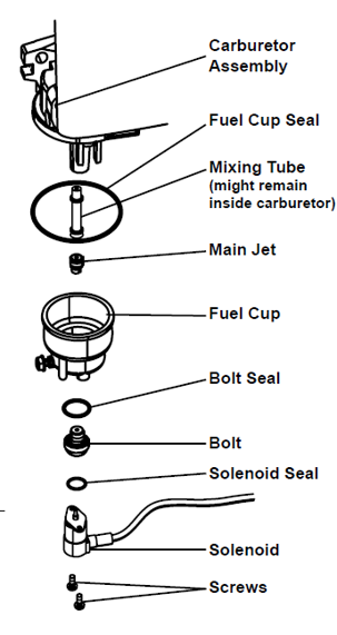
In the center of the carburetor, near the bottom of the carburetor bowl is the main jet.
The main jet supplies fuel to the engine when it is at full throttle.
When the main jet becomes blocked, the engine will stall at full throttle. Once stalled, the governor will close the throttle. At this point the carburetor’s idle circuit will begin to supply fuel and the engine will fire once again and the throttle will return to full.
This cycle repeats over and over, causing the engine to die and surge. Fixing a surging engine is usually a matter of cleaning the carburetor..."

Atomizer
Mixing tube- long cylindrical tube with holes
Tall end which goes into the venture and short end next has a Phillips head to the Main Jet
Float
Needle and hinge pin
Carburetor bowl
Bolt seal, Bolt
Auto Choke Mechanism
Gaskets
Air box
Air filter
Carb Cleaner -vinegar and water - neutralize rust
Does Your Lawn Mower Sound Like It Is Surging?
Grime and dirt can gum up the internal components of your carburetor, making it fail to receive the correct flow of fuel.
Solution: You can take your mower to a small engine repair shop to have the carburetor removed and cleaned.
1.Disassemble the carburetor. For you to reach the carburetor, you’re likely to have to disconnect the air filter, fuel tank, governor control link, breather pipe, and manifold seal and keeper ring.
2. Clean the carburetor with a carburetor cleaner that’s appropriate for your mower engine, paying special attention to the needle valves, orifices, and ports. You’ll need to replace the carburetor if its body is in poor condition or damaged.
3. Once you’ve given the carburetor a good cleaning, reassemble the mower components in reverse order..."
Run on Choke only
Choke is decreasing air and increase vacuum which sucks more fuel in to cylinder.
Cause - Starvation of fuel
Fuel Strainer/Filter Blocks
When choke - Close outer butterfly valve restricts the airflow coming into the carburetor, builds a vacuum in Venture and draws down harder on the jet, pulling more fuel out
Fuel Cap - Vent hole (Breeder valve) create a vacuum Blocked
As air moves down the fuel tank it creates a vacuum, when vacuum builds up it draws air from vent hole to balance the pressure and the fuel will flow.
Air Leak in Fuel Line to Carburetor
It gives you more air to fuel and does not create a good fuel/air combustion.
Inlet manifold gasket leaking/Bolt loosen
Carb adjustment screws
Module 4 - Governor System
Governor main purpose is a feedback controlling mechanism.
It balances the speed of the engine rpm's to adapt to various load conditions.
Steady engine Speed: Governor Flyweights and Governor spring force are balance ;
Loss of engine Speed: Governor spring force exceeds Flyweight Force (Throttle opens to regain speed) Engine overspeed: Governor Flyweight Force exceeds spring force (Throttle closes to decrease the speed)
The governor gear is driven by the crankshaft
The Governor flyweights are attached to the governor gear
These flyweights are hinged and contain a lever that contacts the governor regulating pin
The governor regulating pin transfer motion from the flyweight to the Governor's cross shaft
Purpose:
The governor balances the speed of the engine rpm's to adapt to various load conditions.
Principle of Operation
The governor gear is driven by the crankshaft
the Governor flyweights are attached to the governor gear
These flyweights are hinged and contain a lever that contacts the governor regulating pin
The governor regulating pin transfer motion from the flyweight to the Governor's cross shaft
Increase the speed of the Governor's gear increase the centrifugal force on the governor's flyweights
As the flights moves outwards, they force the regulating pin away from the governor's gear
The regulating pin is in contact with the cross shaft and causes it to rotate
The cross shaft is connected to the governor lever
Summary of Operation
Steady engine Speed:
Governor Flyweights and Governor spring force are balance
Loss of engine Speed:
Governor spring force exceeds Flyweight Force (Throttle opens)
Engine overspeed:
Governor Flyweight Force exceeds spring force (Throttle closes)
Gear mechanism spins the mechanical Governor gear assembly.
It rotates and centrifugal forces causes 2 mechanical counterweights in the Governor assembly to move outwards.
Including the springs and weights
he spring and the mechanism, wether its weights or fan type, work together to hold the set revs.
https://www.youtube.com/watch?v=3jUpb71D3is
Module 5 - Ignition System and Electric
2 types of timing
Electrical - Ignition
Mechanical – Flywheel Key - Fuel at the right time, Valves at the right time, spark at the right time, piston at the right time – all maintain with the Flywheel key.

Flywheel operates weathervane (springs brings it back when it slows down) it controls the governor/carburetor throttle
It controls constant speed of the engine
Works in conjunction with governor spring and idle spring
Flywheel made of aluminum on lawn mower made of cast iron
Aluminum flywheel isn’t heavy enough to maintain momentum of piston going up and down in cylinder, so the flywheel and lawnmower blade is part of flywheel to maintain momentum.
Flywheel fins are not the same in height – it change the harmonics.
Inside flywheel are magnets and as the flywheel spins, it passes in front of a stationary coil, builds up a magnetic field and as it passes the coil it collapse the field and induce a charge to the spark plug where we get our ignition.
Ignition (Spark) Related
Spark plug cap not connected securely
Spark plug electrode wet or dirty
Incorrect spark plug gap
Spark plug cap broken
Circuit breaker trip (electric start models only)
Incorrect spark timing or faulty ignition system
Spark plug cap not connected securely
Spark plug electrode wet or dirty
Incorrect spark plug gap
Spark plug cap broken
Circuit breaker trip (electric start models only)
Incorrect spark timing or faulty ignition system

Troubleshooting
Engine will not start
For combustion to occur you'll need fuel, spark, air and compression.
Fuel Related
No fuel in tank
Cold Engine, Choke is not in Choke position
Gasoline with more that 10% ethanol used
Low quality or deteriorated, old Gas
Carburetor is not prime
Dirty fuel passageways
Carburetor needle stuck, Fuel can be smell in the air
Too much fuel in chamber. This can be cause by carburetor needle sticking
Clogged fuel filter
Ignition (Spark) Related
Spark plug cap not connected securely
Spark plug electrode wet or dirty
Incorrect spark plug gap
Spark plug cap broken
Circuit breaker trip (electric start models only)
Incorrect spark timing or faulty ignition system
Spark plug cap not connected securely
Spark plug electrode wet or dirty
Incorrect spark plug gap
Spark plug cap broken
Circuit breaker trip (electric start models only)
Incorrect spark timing or faulty ignition system
Compression Related
Cylinder not lubricated. Problem after long storage periods
Loose or broken spark plug (hissing noise will occur when trying to start)
Loose cylinder head or damage head gasket (hissing noise will occur when trying to start)
Engine valves or tappets mis-adjusted or stuck
Cylinder not lubricated. Problem after long storage periods
Loose or broken spark plug (hissing noise will occur when trying to start)
Loose cylinder head or damage head gasket (hissing noise will occur when trying to start)
Engine valves or tappets mis-adjusted or stuck
No comments:
Post a Comment